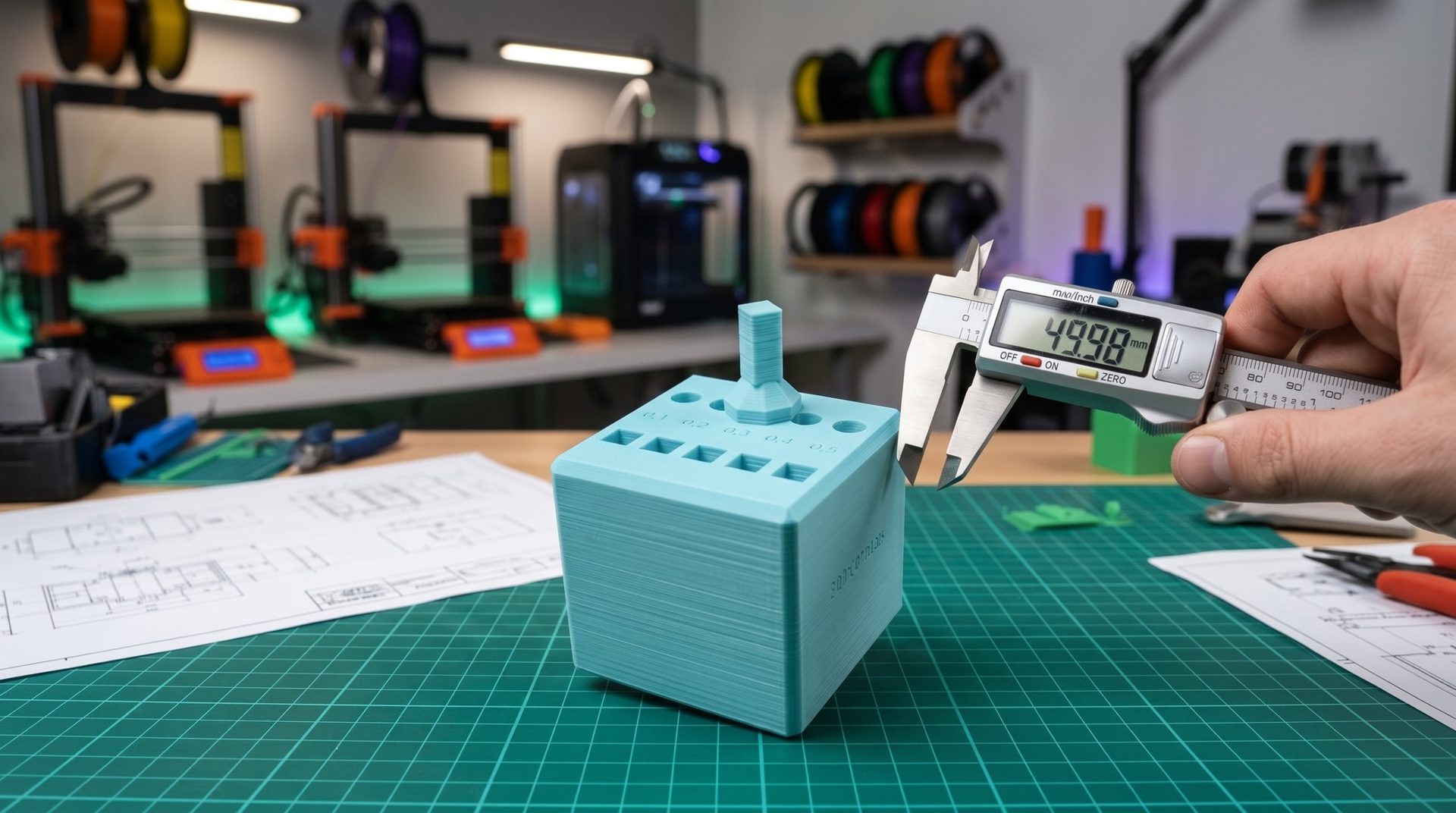
Dimensional Tolerances in 3D Printing: Why Your Part Never Fits Right
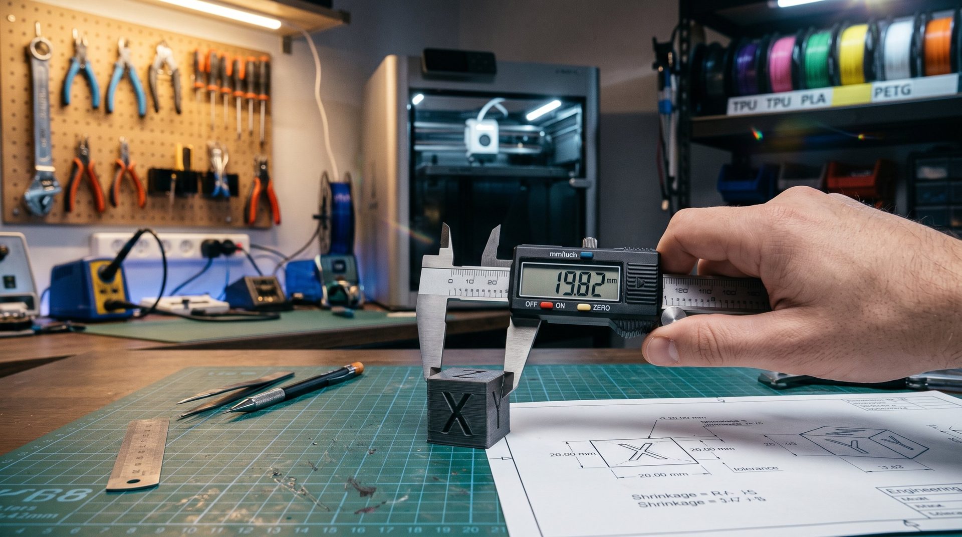
You model a perfect 20.00 mm calibration cube in Fusion or FreeCAD. Once printed and cooled, you measure it with calipers: 19.84 mm in X, 19.82 mm in Y, and 20.02 mm in Z.
For decorative objects, a few tenths of a millimeter go unnoticed. But for a mechanical assembly, a 608 bearing bore, or a tight press fit, it's guaranteed failure: the part is too narrow and the shaft won't fit.
Your first instinct is often to blame the motors or tweak the steps per millimeter (steps/mm) on your printer. That's usually wrong: a modern machine is factory-calibrated with excellent precision. The problem usually comes from the plastic's behavior itself. And to correct your parts, our tolerance calculator is built into this article.
1. Shrinkage: plastic contracts as it cools
Plastic exits the nozzle at over 200 °C and ends up at room temperature, around 20 °C. As it cools, it shrinks, and the part loses a bit of volume. This shrinkage isn't uniform everywhere.
A. Each material has its own shrinkage
Typical ranges in FDM printing, which vary by brand and settings:
- PLA: very low, about 0.2 to 0.5%;
- PETG: moderate, about 0.3 to 0.8%;
- ABS / ASA: higher, about 0.7 to 1.5%, which is why they tend to warp at corners;
- Nylon (PA): high, often over 1.5%. Fiber-filled versions (CF, GF) shrink considerably less.
B. More shrinkage in width than in height
Shrinkage shows mainly in the horizontal plane (X and Y):
- In X and Y, the extrusion bead is stretched along its path. As it cools, it pulls the material lengthwise.
- In Z, the height of each layer is set by the nozzle position, and hot plastic settles. The vertical gap typically stays small.
2. The hole trap: always too small
Holes shrink more than outer outlines, for two reasons:
- Circles become polygons: an STL file breaks each circle into small straight segments that fall inside the true circle. The effective diameter shrinks.
- The bead "cuts" the curves: in a small hole, still-soft plastic tends to tighten toward the center, pushing the wall inward.
Result: an 8.00 mm hole designed for an M8 bolt often comes out around 7.75 mm.
3. The caliper calibration method
A simple 20 mm cube isn't enough. To tell if the error is shrinkage or a constant offset, you need to compare several lengths on the same axis. We've designed a free calibration pyramid for this: three steps of 50, 35, and 20 mm and an 8 mm hole, which prints support-free.
- Print it at 100%, with the material and settings you normally use.
- Measure each step in X, then Y, at mid-height—not flush with the build plate. Then measure the hole.
- If the gap grows with size (for example −0.10 mm on 20 mm and −0.25 mm on 50 mm), that's shrinkage: correct by percentage.
- If the gap is the same on all steps, that's a constant error: correct in millimeters.
- Enter your measurements into the calculator below. Use the 50 mm step for size, and the 8 mm hole for diameter.
Change only one setting at a time, then reprint the pyramid to verify.
4. Settings to use in your slicer
- Shrinkage compensation: in the filament settings (not the printer). In OrcaSlicer, you enter the resulting size as a percentage: 98.5% if a 20 mm dimension prints to 19.70 mm. In recent versions of PrusaSlicer, you enter the shrinkage itself: 1.5%. The slicer then enlarges the part in X and Y without changing flow rate. If not available, scale the object (101.5% here) in X and Y.
- X-Y hole compensation (OrcaSlicer, Bambu Studio): a positive value enlarges only holes, leaving outer contours alone. It's given in millimeters, typically +0.05 to +0.15 mm.
- X-Y outline compensation: shifts all outer faces by the same value, positive or negative. Ideal for fixing a constant error and tuning a press fit.
Adjust only one setting at a time, then reprint the test piece to verify. To test your assembly fits, also see our tolerance test.
Calculate your corrections
Enter your design dimensions and your measurements: the calculator gives you the values to enter in your slicer.
📐 Tolerance Calculator
1. Measure a part (for example the 50 mm step of the pyramid)
2. Measure a hole (optional)
3. Your software
Starting values: reprint your test piece to verify, and adjust only one setting at a time.
Choose a stable material
For precise parts, material matters as much as settings: PLA and fiber-filled filaments move little, ABS and nylon move a lot. Our selector compares 12 filaments based on your needs.