Calibrate Your Mechanical Fits: The 50mm Tolerance Cube & Test Key Guide
Hinge, rotating shaft, sliding drawer, tight fit: whenever a 3D printed object needs to come together, the material complicates things. With plastic shrinkage, extrusion line width, and circles that come out undersized, a 6.00 mm hole never accommodates a 6.00 mm shaft without some play.
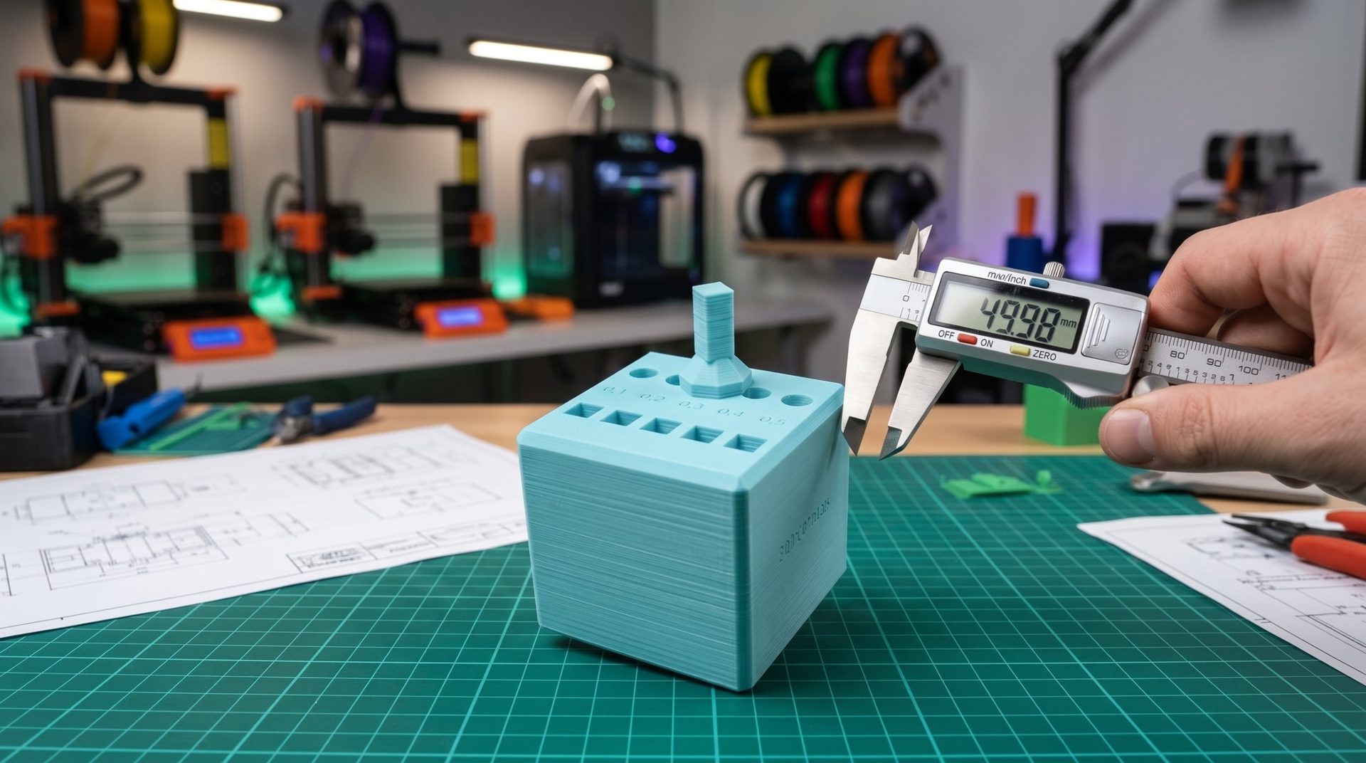
To end the guesswork, we designed a simple test bench: the 50 mm tolerance cube and its test key, both free, printing support-free. In one print, you'll know exactly what play to design into your models.
1. The cube and its key
The system tests both square and round shapes, which don't react the same way.
The cube (50 × 50 × 50 mm)
- On top: two rows of 5 holes running through the cube from top to bottom, 5 round and 5 square.
- The play ranges from 0.1 to 0.5 mm in 0.1 mm steps. Each value is engraved between the two rows.
- The labels: "TOLERANCES" is engraved on the front and "PLAY mm" on the side.
The test key (37 mm tall)
- at the bottom, a square stem of 6 × 6 mm;
- in the middle, a collar for gripping that also serves as a stop;
- at the top, a round stem 6 mm in diameter.
2. Printing it right, support-free
- The cube sits flat on its base. The holes are vertical and run through the entire piece.
- The key prints standing up, square stem on the build plate and round stem pointing up. This way, the round stem is traced in complete circles, just like the cube's holes: the comparison is accurate.
- The overhangs: only the tops of the letters engraved on the sides are "in the air," about 0.6 mm. Any 0.4 mm nozzle handles this with no trouble.
- The settings: 3 walls, 15% gyroid infill, and most importantly no hole compensation for this first test. This way you measure your printer's actual accuracy.
Print with the filament you'll use for your parts: a PETG or ABS won't give the same results as a PLA.
3. The test: finding the right play
Wait until both pieces cool completely, then:
- Round test: slide the round stem into the row of round holes, from the loosest fit (0.5 mm) to the tightest (0.1 mm). Note the smallest hole it enters without forcing.
- Square test: flip the key and do the same with the square stem in the row of square holes.
- Measure the key with calipers: the round stem should be about 6.00 mm.
How to read your results
- The key turns freely: that's a loose fit, for shafts that spin without bearings or print-in-place mechanisms. Usually around 0.4 to 0.5 mm.
- The key slides smoothly without forcing or wobbling: that's a sliding fit, ideal for drawers, slides, and removable covers. Often around 0.2 to 0.3 mm.
- You need to push hard: that's a tight fit, which holds without glue. Often around 0.1 mm.
These values vary by printer, nozzle, and filament—which is exactly what the cube lets you measure on your own setup.
What you'll often notice: the square stem enters at 0.2 mm, while the round stem still binds at 0.3 mm. That's normal: small circles always come out a bit undersized compared to straight shapes. We explain this in our article on dimensional tolerances.
4. Calculate your adjustments
Enter your results: the calculator tells you what play to design into your models and what correction to enter in your slicer.
🔑 Play calculator
1. Your results with the cube
2. What you want to achieve
Starting values: test them on a small test piece before printing a large assembly.
The right filament for your mechanisms
For parts that rub or rotate, material matters as much as play: some filaments slide better and wear less. To measure your filament's shrinkage too, use our calibration pyramid. And to choose the right material, our selector compares 12 filaments, including a "friction" criterion.