3D Print Strength: Stop Parts From Breaking Clean
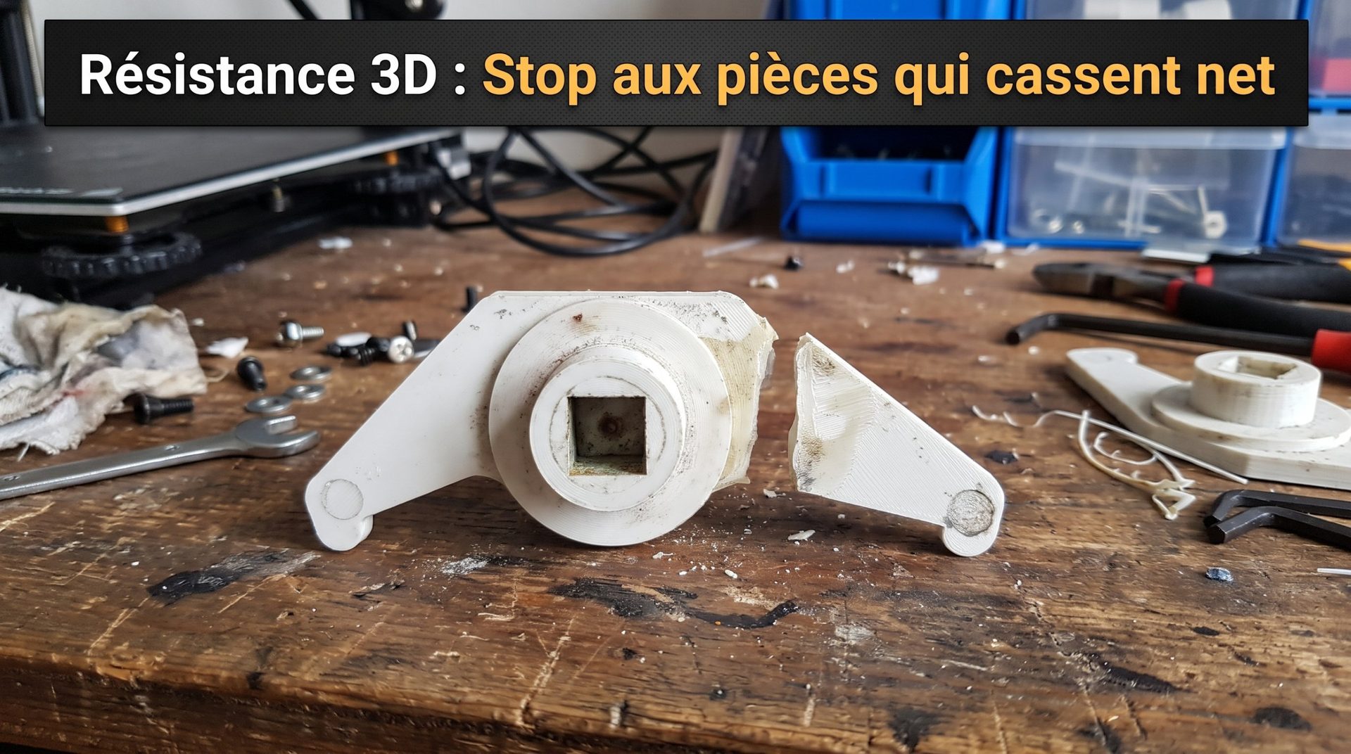
You're designing a workshop hook, a hinge, or a lever. After several hours of printing, you tighten the fasteners, apply moderate force… and a sharp crack echoes: the part snaps in two along a perfect line, as if cut with a utility knife across a single layer.
In the vast majority of cases, the culprit isn't your filament quality or under-filling. The problem stems from a physical property of Fused Deposition Modeling (FDM): anisotropy—meaning the material has different strength depending on the direction of the applied force.
A 3D printed part doesn't behave like an injection-molded part, but like a wooden beam: stressed along the grain (here, the plastic beads), it handles heavy loads; stressed perpendicular to the layers to separate them, it fails without warning.
Anisotropy: Strong Beads, Weak Bonds
An injection-molded part is nearly homogeneous: it resists about the same in all directions (X, Y, and Z). In FDM printing, each deposited bead has a different story:
- In the horizontal plane (X/Y): melted plastic forms a continuous bead, with polymer chains aligned along the nozzle path. This is the strongest direction, like wood grain.
- On the vertical axis (Z): the nozzle deposits a hot bead on an already-cooled layer. Strength depends solely on the hot plastic's ability to reflow and bond to the layer below.
Result: depending on filament and settings, inter-layer strength often represents only 40 to 80% of that measured along the bead direction. Any force trying to peel or tear layers apart will start a crack at that weak bond and propagate all at once.
3 Forces to Consider Before Printing
Part orientation on the build plate must never be chosen for convenience or to save supports—only based on the actual forces it will face.
| Applied Force | Orientation to Avoid | Recommended Orientation | Result |
|---|---|---|---|
| Tension (hook, rod) | Vertical force along Z axis: peels layers apart | Horizontal force in X/Y plane: pulls along beads | Significantly stronger |
| Bending (lever, hook) | Lever arm printed upright | Part flat or on its side | Significantly stronger |
| Screw tightening | Screw driven through layers | Screw along wall axis, or brass insert | No splitting at tightening |
4 Design Tips for Parts That Don't Break
Increasing infill from 20 to 80% won't save a poorly oriented part: you're just adding weight without strengthening the weak inter-layer bond. Strength is decided at the modeling stage.
1. Lay the Part Flat or Tilt It 45°
Any part under tension (hook, rod, link) must be oriented so its outer walls follow the load direction. Laying the part on its side may require supports, but ensures continuous material along the stress line.
2. Round Internal Corners
A sharp 90° inside corner concentrates stress at one point, often right at a layer junction: that's where the crack starts.
- Eliminate sharp internal corners on load-bearing parts.
- Add a fillet (radius) of at least 2–4 mm, or a chamfer. Stress spreads across dozens of layers instead of one.
3. Split the Part Into Multiple Pieces
When a part faces forces in multiple directions at once (a load-bearing bracket in both shear and bending, for example), no single orientation is ideal.
- Divide it into two sub-assemblies in your CAD software.
- Print each piece in its strongest orientation.
- Assemble with a tenon and mortise, dovetail, or bolt.
4. Stop Screwing Directly Into Plastic
A screw driven hard into printed plastic acts like a wedge: pressure forces layers apart until rupture. For strong, reusable assembly, install brass threaded inserts with heat using a soldering iron: the plastic reflowed around the insert locks it without creating splitting tension. Nuts pressed into a hexagonal cavity are a good alternative.
Slicer Settings: Better Inter-Layer Bonding
When part geometry blocks ideal orientation, a few slicer tweaks significantly strengthen inter-layer bonds:
- Raise temperature by 5–10 °C: hotter plastic refuses better to the layer below.
- Reduce cooling fan speed: too much airflow freezes the layer before the next pass. Lower it to the minimum your bridges and overhangs tolerate.
- Switch to a larger nozzle: a 0.6 or 0.8 mm bead holds heat longer than 0.4 mm. Estimate time saved with our nozzle converter.
- Add walls instead of infill: four or five walls at 20% infill often make a stronger part than two walls at 70% infill. For the right pattern, read our article on infill patterns.
And of course, pick material suited to the load: our guide on choosing filament for strong parts helps you decide.
Workshop Talk: Your Most Dramatic Breaks
- What part did you watch snap cleanly before you realized the Z-axis was to blame?
- Ever redesigned an entire assembly into multiple pieces just to orient each one right?
- For fastening, do you prefer heat-set brass inserts or nuts pressed into a hex pocket?
Share your worst breaks and design tricks in the comments!