3D Printing Infill Patterns: The Art of Combining Strength and Efficiency
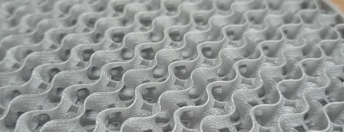
In FDM 3D printing (Fused Deposition Modeling), parts are rarely printed completely solid. An internal structure, called infill, is created inside the object. This infill is a crucial parameter that determines not only the strength and resistance of the part, but also its weight, print time, and the amount of material consumed.
Choosing the right infill type and density is a subtle balance that must match the functional requirements of your part. Let's dive into the different infill patterns and their impact on strength.
What is Infill and Why is it Essential?
Infill is the internal pattern of a 3D printed object. The slicing software generates this structure based on your parameters. It's essential for several reasons:
- Structural Support: It supports the upper layers of the part and prevents deformation or collapse of the walls.
- Strength and Rigidity: A part with adequate infill will be more resistant to mechanical stress (compression, tension, bending, torsion).
- Part Weight: Lower density infill significantly reduces the final weight of the object.
- Material Consumption: Higher infill uses more filament.
- Print Time: The denser or more complex the infill, the longer the print will take.
Key Factors Affecting Strength Beyond Infill
Before detailing the patterns, it's important to note that other parameters play a major role in the overall strength of the part:
- Number of Perimeters (or Wall Thickness): The outer walls (shells or perimeters) are often the most important factor for bend and break resistance. Increasing the number of perimeters will often have a more significant impact on strength than an equivalent increase in infill.
- Material: The type of filament (PLA, PETG, ABS, Nylon, PC, Composites) is the primary determinant of resistance.
- Layer Height: Thinner layers can improve cohesion between layers.
- Print Orientation: The direction of layers relative to applied stress is crucial. Parts are generally stronger along the layers than perpendicular to them.
The Most Common Infill Patterns and Their Strength
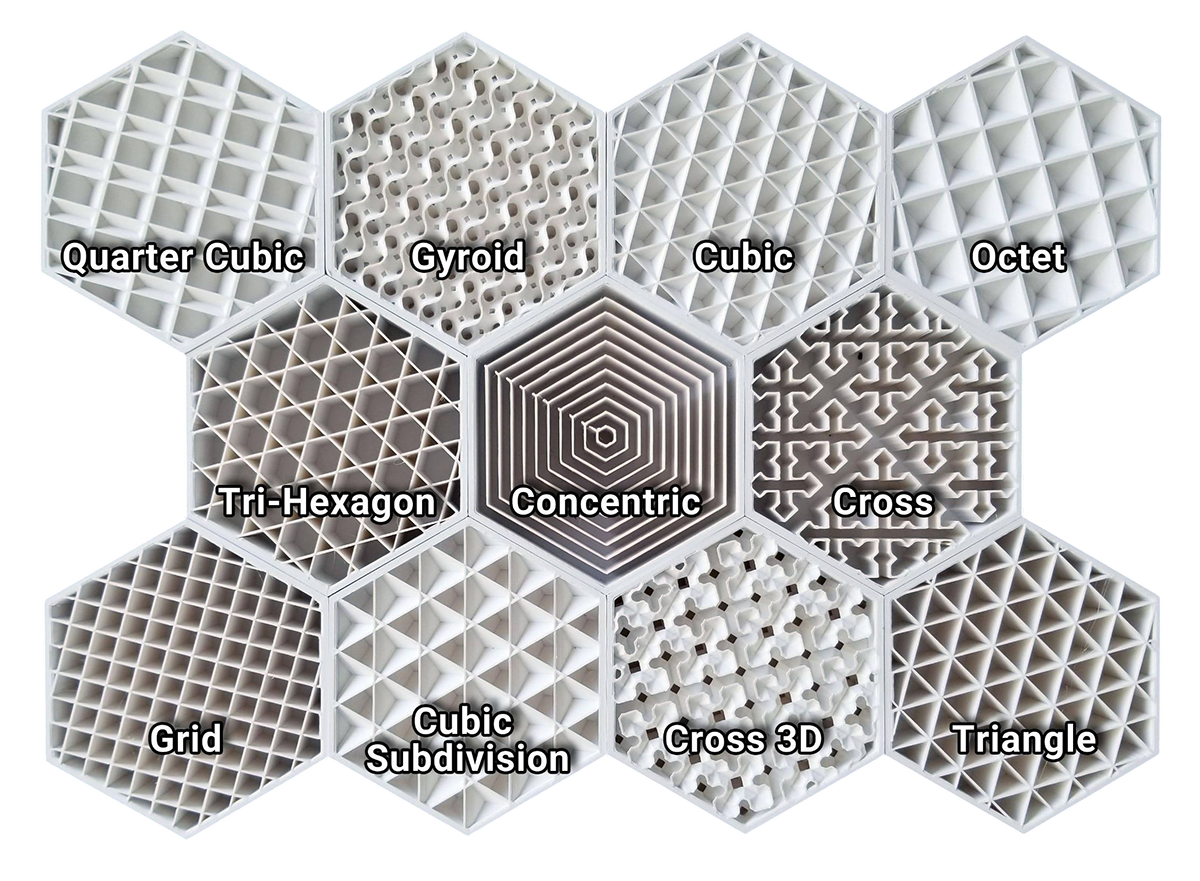
Here's an overview of the most frequently used infill patterns in slicers and their characteristics in terms of resistance:
Lines (Line / Rectilinear)
-
- Description: Simple pattern of parallel lines that alternate from one layer to the next (often at 90°).
- Strength: Good in the direction of the lines, but weaker in perpendicular directions. Non-isotropic. Fast to print.
- Use: Rapid prototyping, parts not subject to high stress.
Grid
-
- Description: Parallel lines that intersect at 90° on the same layer, forming a grid pattern.
- Strength: Better than simple lines, but can create "air pockets" under upper layers (cushion effect).
- Use: General purpose, simple support parts.
Triangles
-
- Description: Pattern of lines that intersect to form regular triangles.
- Strength: Good balance between strength and material consumption. Triangles are very stable structural shapes. Offers more balanced resistance.
- Use: Parts requiring good strength without being critical.
Honeycomb / Hexagon
-
- Description: Creates hexagonal cells, mimicking the structure of a honeycomb.
- Strength: Excellent strength-to-weight ratio. Very good force distribution thanks to the cellular structure that resists compression and torsion well. Considered one of the best for overall strength.
- Use: Functional parts, structural components, supports for moderate to high loads.
Gyroid
-
- Description: A complex 3D structure, non-linear and interwoven, resembling a mathematical sponge.
- Strength: Very high isotropic resistance (uniform in all directions). Excellent stress distribution. Allows good drainage of excess resin in SLA/DLP prints.
- Use: Parts subjected to multidirectional stress, lightweight aerospace components, aesthetic parts with transparent surfaces.
Cubic / Cubic Subdivision
-
- Description: 3D pattern made of stacked cubes (or cube subdivisions).
- Strength: Offers very good overall strength, particularly resistant to compression and impact forces. Also isotropic in its 3D versions.
- Use: Parts requiring high resistance to shock and crushing.
Concentric
-
- Description: The infill follows the outer contours of the part, reducing in size with each line toward the center.
- Strength: Very good for compression perpendicular to layers. Ideal for flexible parts (TPU) as it respects material flexibility. Less strong for lateral forces.
- Use: Flexible parts, caps, gaskets, shells, where flexibility or compression is paramount.
Cross 3D
-
- Description: Some slicers may offer more advanced patterns that incorporate "cross" elements in three dimensions, or variations of the grid pattern designed to provide better force distribution. This could look like "X" shapes or crosses repeating and overlapping to create more robust interconnection across layers.
- Strength: Aims to provide more isotropic strength (uniform in all directions) by distributing loads more efficiently through 3D space. These patterns are typically more resistant than 2D grids.
- Use: Functional parts requiring good resistance in all directions, but potentially less optimized for weight than patterns like Gyroid or 3D Honeycomb.
Infill Density: The Percentage That Changes Everything
The infill density (expressed as a percentage, from 0% to 100%) is the most intuitive parameter:
- 0% (Hollow): For purely aesthetic objects, or lightweight enclosures. Very fast and economical.
- 10-20%: Often sufficient for most common functional parts that aren't subject to high stress. Good balance.
- 20-40%: For parts that need to support moderate loads or require some rigidity.
- > 40%: Reserved for parts subjected to significant stress. Beyond 60-70%, strength gains are marginal compared to increased time and cost. At this point, it's often more efficient to increase perimeters or change material.
- 100% (Solid): For critical parts requiring maximum resistance, or if you're working with flexible materials that need mass to function as seals. Significantly increases time and cost.
The Right Choice for the Right Application
Choosing the right infill is an informed decision. For a part requiring optimal strength, prioritize a pattern like Honeycomb or Gyroid with a density between 20% and 40%, and make sure you have enough perimeters (at least 3-4). For simple prototypes, 10-15% in lines or grid will suffice.
Experimentation is key! Don't hesitate to print samples with different settings to understand how each pattern and density affects your parts' performance. It's by mastering these parameters that you'll turn failures into successes and your 3D prints will reach optimal strength levels.