From Text to 3D File: AI and the Text-to-CAD Revolution
Generating a parametric, functional 3D model from a single sentence: it's one of the most exciting challenges in computer-aided design. Once confined to science fiction, turning a "prompt" into an engineering file is becoming a reality.
But between marketing promises and real workshop constraints, how does Text-to-CAD actually work? What are its strengths and limitations, and how do you integrate it into your workflow? Let's dive in.
1. The Essential Distinction: Text-to-Mesh or Text-to-CAD
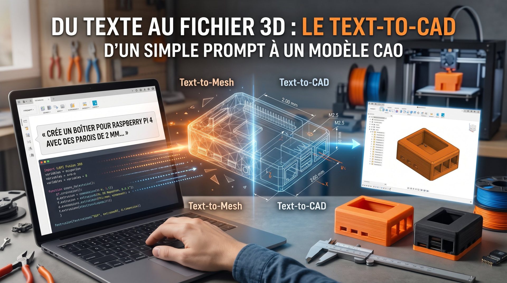
Don't confuse two very different technologies. When the general public talks about generative 3D AI, it's almost always Text-to-Mesh. For engineering and 3D printing functional parts, Text-to-CAD is what matters.
| Feature | Text-to-Mesh (Classic Generative AI) | Text-to-CAD (Parametric CAD) |
|---|---|---|
| Reference Tools | Tripo AI, Meshy, Rodin, CSM | Zoo Text-to-CAD (formerly KittyCAD), Claude or ChatGPT via CAD scripts |
| Output Formats | STL, OBJ, GLB | STEP, parametric scripts (Python, OpenSCAD, CadQuery, KCL) |
| Geometry | Approximate triangle mesh | Exact geometry (B-Rep): perfect cylinders and planar faces |
| Precision | Visual, sculpted, dimensionless | Precise dimensions and geometric constraints |
| CAD Editing | Very tedious (frozen, heavy mesh) | Complete (editable history, sketches, and features) |
Meshes work great for figurines, video games, or artistic rendering. But to house a ball bearing, respect a bolt spacing, or manufacture a mechanical part, the exact geometry of a CAD model remains irreplaceable.
2. How Text-to-CAD Works Today
To get a usable model in Autodesk Fusion, FreeCAD, or SolidWorks from a sentence, two approaches dominate. Both are fundamentally based on code generation.
Approach A: An AI Assistant That Writes the Script
Today, this is the most flexible and accessible method:
- The Request: you describe your need in plain language, for example: "Create an enclosure for Raspberry Pi 4 with 2 mm walls, 4 bosses for M2.5 screws at the corners, and openings for USB-C and micro-HDMI ports."
- The Code: an AI assistant like Claude writes a script (in Python for the Autodesk Fusion API, in OpenSCAD, or in CadQuery).
- Execution: the script runs in your CAD software, draws sketches, applies dimensions, and performs operations (extrusions, holes, fillets).
- The Result: a parametric part with its construction history, editable as if you'd drawn it yourself.
Some assistants can even control the software directly, as we demonstrated with Claude connected to Autodesk Fusion.
Approach B: Dedicated Text-to-CAD Tools (e.g., Zoo)
Specialized services like Zoo Text-to-CAD transform your request directly into a mechanical part. Behind the scenes, Zoo writes the model in its own parametric language (KCL), creating a true editable construction history, then exports it as STEP or STL. A free tier lets you test it within a monthly quota.
3. Current Limitations
The approach is attractive, but mechanical design demands a rigor that AI doesn't yet fully master:
- Language Ambiguity: a few lines of text can't contain all the constraints of a real part: fits, assembly clearances, chamfers, radii to avoid stress concentrations…
- Complex Geometries: once a part combines several tricky operations (grooves, ribs, intersecting fillets), the generated script may fail or produce an incorrect shape.
- No Real-Time Mouse Tweaking: in classic CAD, you change a dimension and see the result instantly. In Text-to-CAD, every fix requires rewording the request or reworking the part by hand.
- Single Parts Only: these tools handle one part well, far less so with assemblies of multiple pieces. And none guarantee mechanical strength of the result.
4. The Right Approach: AI for the Sketch, You for the Finish
Today, AI's value isn't replacing the designer but eliminating the blank-page syndrome. The most effective workflow looks like this:
Written Brief → AI-Generated Script → 80% Draft → Hand Finishing (20%) → Export STEP or STL → Print
- AI Draft: in seconds, it lays down the overall structure, reference planes, main dimensions, and parameters.
- Hand Refinement: you open the part in your usual software to tweak fillets, dial in assembly clearances (often around 0.2 mm for FDM printing—verify on your machine) and check strength. Our guide on 3D printing tolerances will help you find the right value.
With this hybrid method, you save huge amounts of time on repetitive tasks while keeping full control of your part's dimensions. To pick the software that will refine your drafts, check our 3D modeling software guide.